
Aim
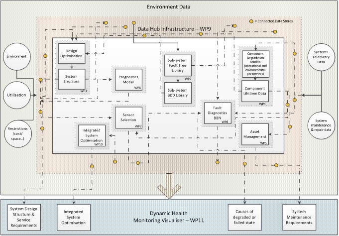
Figure 1: Overall integrated structure of RESILIENCE
The overall aim of this project is to produce an intelligent and dynamic infrastructure to support the fuel cell system design and operation to achieve optimal reliability throughout its life, in a given market with specified limitations on the available resources.
The overall project aim will be achieved by addressing four objectives: robust design, asset management, diagnostics and intelligent infrastructure.
- (i) Achieve the most robust design through the initial design process when component selection, redundancy levels and maintenance service intervals will be fixed to give optimal reliability performance whilst accounting for limitations on resources, such as system weight, system dimensions, initial system cost, and functional requirements including range, performance and whole life costs.
- (ii) Establish a dynamic asset management strategy to minimise the occurrence of system failures and maximise operational reliability and availability. This will be achieved by understanding the degradation of the system elements and performing maintenance in a way which avoids unexpected breakdowns. Maintenance will, where possible, be performed on a predict and avoid strategy rather than a reactive approach which responds to the occurrence of failures.
- (iii) Establish the diagnostic capability to identify the causes of failed or degraded system performance. For some failure modes the identification of the degraded performance will enable correction before the failure materialises. In cases of failure determining the causes will facilitate high availability.
- (iv) Establish a real-time dynamic and adaptive intelligent infrastructure to manage large terse data sets and to enable interrogation of the information for system level informed decisions in dynamic and changing situations.
Based on Figure 1, identifiable objectives to produce the capabilities and methodologies which, when combined, will achieve the overall project aim, are listed in Table 1. During and at the end of the project the methodologies will be proved and demonstrated by application to a practical fuel cell design and operational requirements provided by the collaborator, Intelligent Energy.
Work Packages & Objectives
For maximised impact of the research, the first stage provides the commercial viability and will generate a common understanding across all aspects of the project, through knowledge elicitation on an applied fuel cell system. Through liaison with the industrial collaborator, Intelligent Energy, knowledge will be gained of the overall functionality of the fuel cell, its system structure and the functioning and failure modes of all of the sub-systems including: system control, hydrogen management, power management and environmental monitoring. A failure analysis (FMEA) of the system modules will be used to identify the component level failure modes and their effects on system and sub-system operation. How the potential design variations relate to the functional requirements, environmental conditions and practical implementation issues would also be established. Telemetry operation and the possibilities for data monitoring direct from the fuel cell units and the data which would become available through the servicing, support contract, spares supply and maintenance network would also be discussed with the industrial collaborators and the bounds for the fault diagnostic and asset management activities defined. Initial reference models will be constructed to allow evaluation of each of the future WP activities.
Fault Tree Analysis will be used to develop the causes for all of the system module failure modes. Events within the tree diagrams, the fault trees constructed can represent all possible system structures. Since these failure logic diagrams have the potential to become very large, and to enable the longer term optimisation objective requiring many potential design variants to be evaluated, a fast, state-of-the-art, analysis method (Binary Decision Diagrams, BDDs) will be employed in their quantification. BDDs are fast, accurate and efficient and have been shown to provide the capability for design optimisation. The ordering placed on the component failure events which appear in the fault trees required for an efficient BDD analysis would be established at this stage. Data for the component failure rates would be imported from the data store created by WP4 where the latest, continually updated, values are available. Models generated will be evaluated by the utilising the initial reference models from WP1.
The failure models developed in WP2 would be combined into a fuel cell unit model and this would be embedded within a Genetic Algorithm multi-objective framework. Constraints would need to be expressed to ensure that the design selected would meet the performance requirements in the operational environment and that the system could be physically housed due to any weight and space restrictions. With the optimisation capability developed (written in C++) it could then be applied to set the component selection, the redundancy allocation and the servicing requirements in the fuel cell design. Other limitations on the design selected, such as the initial cost or the life cycle cost, could be included either as a hard constraint or as one of the multiple objectives in the optimisation. Comparison and evaluation from base line initial reference models will be used to determine the optimisation potential
The aim of this WP is to produce methods to establish probabilistic models that govern how components degrade or fail related to the parameters defining their utilisation and environment characteristics. Utilisation and environment data will be obtained by telemetry directly from each fuel cell unit in the field. Component lifetime data will be gathered from service, maintenance and repair operators. The lifetime predictions will be constantly updated as more data becomes available. Initial reference model components will be used for evaluation and testing purposes.
Once the component deterioration models have been derived in WP4 then asset management strategies are required, determining at what point these components or line replaceable units (LRUs) need to be replaced in order to control the risk of in-service failure to an acceptable limit. Where redundancy exists in a system, and failure can be tolerated, the system structure needs to be considered when evaluating the risk the failure poses. Once these replacement intervals have been established for each component they will be grouped and rationalised to periods which minimise customer inconvenience. The methodology to set the renewal conditions will be implemented in software to enable the constant updating of the strategy as the data quantity increases, and operating or environmental conditions change. The method will be tested and validated using the Intelligent Energy initial reference models.
The aim of this WP is to predict the symptoms which will be observed for every potential component level fault condition. A dynamical model of each sub-system will be produced which will predict the changes in the sub-system process variables resulting from the occurrence of each component failure mode. By systematically introducing the component failure events, process variable deviations can be recorded. The simulation software developed in this WP will use the Petri Net (PN) approach.
It will be impractical to feature the number of sensors required to exactly isolate the precise component failures causing each system fault condition. As such a list of potential failures will be deduced. The number of sensors installed in the system will be a trade-off between the cost of the sensors (plus their maintenance) and the value of the information they produce to the fault diagnostics process. To support sensor selection, information indices will be developed to represent the value of the information they provide. The measures will consider sensor groupings as the value they have needs to be considered in terms of what they add beyond that provided by other sensors. The methodology would also account for the likelihood of each of the failure events (obtained from WP4).
The fault diagnostic approach to be used will be the Bayesian Network. Fault trees, developed in WP2, will be used to overcome the difficulties in Bayesian network construction. For application to fuel cell systems in real-time this method would need to be extended to address the following requirements: i) Dynamics need to be taken into account as symptoms, from the same failure conditions will change over time; ii) The time duration between the occurrence of multiple faults. On the first fault occurrence all symptoms will be consistent with this fault alone. The occurrence of other failures may then change or mask these symptoms. The time duration between the occurrence of multiple failure events will affect the symptoms observed. Successful diagnosis of the causes will require the consideration of the inter-arrival time of the faults. A pattern recognition approach, as described in, will be used to form the basis of the fault diagnostics tool as opposed to the Dynamic BBN methods which will not cope with the size and complexity of the systems and the need for real-time implementation.
An ontology will be developed to form the foundations for the Data Hub Infrastructure, for system level integration. It will be created by developing semi-automated node and linking techniques to increase efficiency and ensure it can be adaptive to changing situations. Outputs from the sub-system analysis, as outlined in the requirements analysis of WP1, will feed back into the ontology and the system will provide new ontological links and update existing data. It will be developed and utilised differently to ‘typical’ ontologies as it will use a layered approach providing direct mapping to data stores to aid with cataloguing the vast volumes of real-time terse data and will incorporate the dynamic relationship between the data sets and the models developed in WPs 2-8. Compatibility of the semantics between source and target systems will be aided by the use of XML.
The sub-system outputs from WPs 2-8, through interrogation of the ontology (WP9), will determine the critical quantifiable lifecycle process characteristics that relate to the inherent performance drivers. This will allow rapid identification of significant factors and complex interactions, and show overall system performance. A further layer will be added to the ontology to provide an adaptive integrated Bayesian network infrastructure that will be used to analyse overall system performance and predict areas for optimisation in the future cell utilisation strategy for extended lifetime performance. The environment created will enable a dynamic or ‘living’ capability where updates in the outputs would be produced in response to the evolving data gathered.
With large terse information being outputted from WP s 2-8 a visual system to quickly interpret these results to monitor the health of the sub-systems and overall system will enable a timely better understanding of the performance. The visualiser will integrate the outputs from the design and diagnostic work packages and would aid the future fuel cell design and health monitoring capability.
This work package would demonstrate the integrated approach developed in the research programme for fuel cell design and development. The software implementation of the methodologies for each stage of the process would be applied to an example fuel cell requirement provided by Intelligent Energy.